PROTEUS VISUAL DESIGNER
Visual Designer for Arduino™ AVR and Raspberry Pi®
Drag • Drop • Play
Proteus Visual Designer combines world class Proteus VSM simulation with an easy to use flowchart editor and a gallery of virtual hardware to provide a truly integrated and intuitive development environment for Arduino and Raspberry Pi
Four Steps to (Drag, Drop and Play)
- Peripheral Gallery full of ready-made Arduino™ Shields or Raspberry Pi Hats.
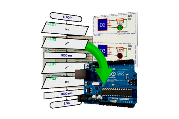
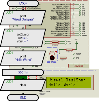
- Drag and Drop Programming with Flowcharts.
- Compile, World Class System Level Simulation, Measurement and Debugging.
- Transfer to the physical hardware at the press of a button.
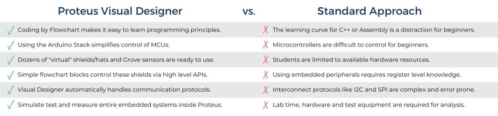
- Advantages of Visual Designer
Learning about microcontroller architecture or embedded systems can be daunting because the detailed knowledge required to drive the electronics often distracts from the principles being taught. Visual Designer takes a different approach, building on the popular Arduino™ and Raspberry Pi philosophy and further removing low level complexity from both the software language and the hardware design. This makes it easier to learn core concepts more effectively and quickly get real projects working
- Main Characteristics of Visual Designer:
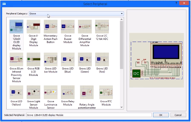
Simplifying Hardware Design
Drag • Drop • Play
Hardware in Proteus Visual Designer starts with the Peripheral Gallery. This contains dozens of ready-made schematic circuit blocks corresponding to real Arduino™ shields or Raspberry Pi Hats. It also includes dozens of Grove modules and ready made sensors and breakout boards. The user simply selects the peripheral(s) they want from the gallery and Visual Designer then.
- Auto-places the circuitry on the schematic.
- Adds the external peripherals to Visual Designer.
- Provides simple methods that you can drag and drop onto the flowchart to control the hardware.
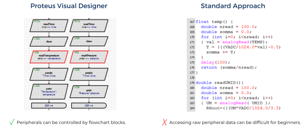
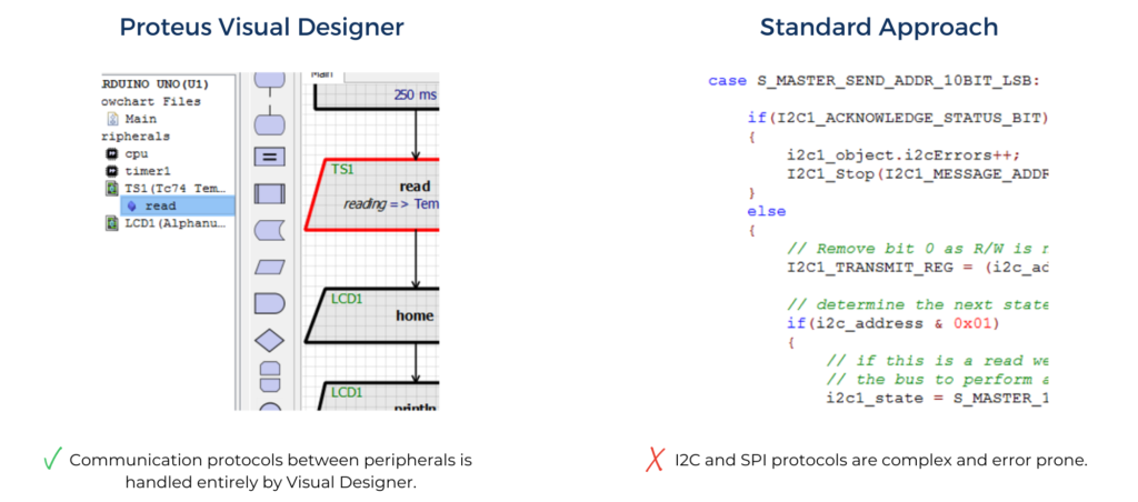
Simplifying Software Design
The Visual Designer Environment is designed to simplify the task of creating a working program. It does this by providing high level access to a whole range of embedded peripherals, guiding and validating expression entry and replacing a programming language with an easily created flowchart.
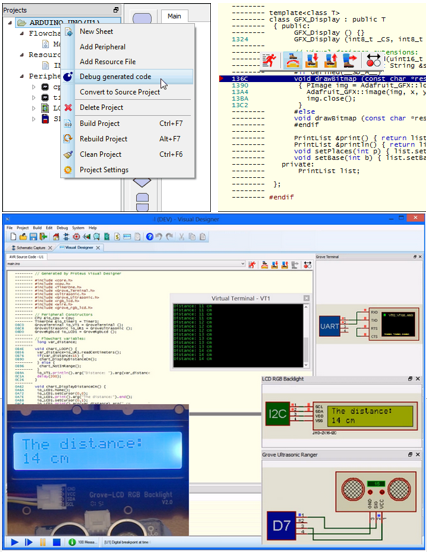
System Simulation
Having added the hardware peripherals and drawn the flowchart the next step is to test that it works and debug it if (when) it does not. This is an area in which Visual Designer truly excels as it is built on top of the Proteus VSM simulation engine.
The entire embedded system can be simulated at the press of a button and you can then interact with it in real time using on screen indicators such as LED and LCD displays and actuators such as switches and buttons.
If something isn’t working properly or you want to analyse your program in more detail, Proteus also provides extensive debugging facilities including breakpoints, single stepping and variable display at both Flowchart and Arduino C++ or Raspberry Pi Python level
Measurement and Analysis
It is often useful for both the Instructor and the student to analyse the signals and waveforms used in the circuit. With Visual Designer this does not require any hardware and works directly on the simulating schematic either on the PC or on the projector in the classroom. Simply place and wire the instrument of choice onto the schematic and then run the simulation.
The following instruments are all supplied as standard with Visual Designer:
- Fully featured 4-channel DSO with measurement cursors.
- Counter/Timer instrument measures time intervals and signal frequency.
- DC and AC Voltmeters and Ammeters.
- Dual mode (master/slave) SPI protocol analyser.
- Pattern Generator for creating 8-bit by 1k bytes digital data streams.
- 40-Channel Logic Analyser with capture buffer and measurement cursors.
- RS232 Terminal with a configuration baud rate,data/stop bits and polarity.
- Dual mode (master/slave) I2C protocol analyser.
- Signal Generator to inject square, saw-tooth, triangle and sine waves.
Transfer to the Physical Hardware
When the testing and debugging of the project is complete, the next step is to deploy the program onto the real hardware. Visual Designer can help with this as well.
In the Arduino case there is a direct interface to the AVR® programmer.All the user has to do is plug in the programming cable, configure the programmer and then press a button to transfer the flowchart program to the real Arduino™ board.
In the Raspberry Pi case a one-time configuration process is required to set up the Raspberry Pi to work with Proteus. After that, the programming interface inside Visual Designer can be used to wirelessly program the Raspberry Pi with the press of a button.
Advanced Writing Code
At some point, if users become more comfortable with programming principles, they may want to write code and control the hardware at a lower level. Visual Designer helps with this transition in two ways:
- Debug any flowchart program with its Arduino C++ source code or Raspberry Pi Python code.
- Convert any flowchart program into an Arduino or Raspberry Pi sketch.
For advanced users the Proteus VSM product range is the natural progression. Working inside the same familiar software environment as Visual Designer, users can learn how to code for different architectures (8/16/32-bit) from a variety of different silicon vendors, designing and simulating real embedded systems from first principles.